
Collaborative Robot-Based Pick & Place Assembly of Screw-Mounted Connectors on Product Enclosures
English translation
ARC Lab: Physical AI, Robotics, and Smart Manufacturing
Paper Title | Collaborative Robot-Based Pick-and-Place Assembly of Screw-Mounted Connectors on Product Enclosures | |
Project Leader: Narbeh Nahapetian | Authors (in publication order): Garik Harutyunyan, Vahan Poghosyan | |
Project Base Information | |
Primary Proposal Submitted Date: | Paper Submission Date: Aug. 2026 |
ARC Category: ☐ EB-ARC ☑ IB-ARC ☐ RB-ARC | Duration: - |
Sponsors (if any): | Project Assets Available: ☑ Yes ☐ No |
Team Members: Garik Harutyunyan Vahan Poghosyan | POC Developed: ☑ Yes ☐ No |
Project Type: ☑ Process Improvement ☐ Automation ☐ AI/ML ☑ Manufacturing ☑ Robotics ☐ Hybrid ☐ Embedded Systems ☐ Others ...... | |
Abstract
This paper presents the development and evaluation of an automated pick-and-place assembly system for screw-mounted connectors on product enclosures using a DOBOT CR3A collaborative robot. Developed as an industrial based proof of concept (POC), the system demonstrates a reliable, low cost assembly setup operating without machine vision.
The physical architecture integrates custom 3D printed component trays for structured part feeding and a two part positioning JIG featuring a magnetic coupling mechanism to ensure precise enclosure registration. Programming was implemented through Dobot Studio Pro's graphical interface, combining pre calibrated positioning logic with passive mechanical compliance to achieve smooth connector insertion. The resulting setup validates a repeatable robotic assembly workflow, establishing a practical framework for educational training and low cost industrial deployment.
Keywords
Collaborative Robots (Cobots), DOBOT CR3A, Pick and Place, Assembly Automation, JIG Design, Smart Manufacturing.
Executive Summary
Manual assembly of high density connectors on product enclosures is often labor intensive, prone to human error, and inconsistent. While traditional industrial automation offers a solution, integrating complex multi robot lines and expensive machine vision systems can be cost prohibitive for small to medium enterprises and educational labs.
This project demonstrates a low cost, repeatable collaborative assembly workstation using a 6-DOF DOBOT CR3A cobot to perform pick and place operations for screw mounted connectors on a sample enclosure ("Mixed Connection Board"). Operating without a machine vision system, the setup relies on structured mechanical fixtures and calibrated software positioning to maintain accuracy. The resulting Proof of Concept (POC) proves that precise, visionless cobot assembly can be achieved through clever mechanical registration and practical programming.
Industrial Problem Definition
In modern electronics assembly, manually inserting asymmetric, screw mounted connectors into circuit boards is a repetitive and error prone process. A primary technical hurdle stems from component geometry: connectors placed in feeding trays naturally assume arbitrary angular orientations. Without an automated mechanism to detect and correct this rotational offset, the insertion of tight tolerance, asymmetric connectors can result in mechanical binding, pin damage, or improper seating.
While high-end industrial automation solves this using multi axis vision systems, such setups are cost prohibitive for small scale manufacturers and educational labs. This project addresses the challenge by developing a low cost workstation that validates spatial trajectory execution and passive mechanical alignment, while isolating rotational orientation as a key requirement for future sensor integration.
Existing/Background and Current State
Prior to starting the assembly automation project, the team's operational state involved foundational familiarization with the Dobot CR3A platform. The project commenced with an in depth technical review of the official documentation suite, which included the CRA Basic Training, Dobot CRA Series Hardware User Guide, and Dobot Studio Pro User Guide.
Key elements from the initial evaluation phase included:
● Hardware Orientation: The Dobot CR3A is a 6-DOF collaborative manipulator featuring six rotary joints and integrated physical control buttons directly on its tool head (enabling hand-guiding, trajectory recording/playback, end control, and status indication).
● Programming Mode Selection: Dobot Studio Pro supports two interchangeable programming modes: text-based Lua scripting and a graphical block-based interface. After evaluating project requirements, the graphical environment was selected to facilitate intuitive logic building and rapid teaching via the end-effector buttons.
● Baseline Validation: To establish motion control reliability and verify kinematic repeatability, the initial program written was a basic pick and place routine that transferred a primitive cube from Position A to Position B.
This initial phase confirmed software-hardware communication and established the functional baseline required before introducing custom tooling, component feeding, or target enclosures.
Project Objectives
The primary objective of this project is to develop and evaluate a low cost, visionless collaborative assembly workstation using the DOBOT CR3A cobot to perform pick and place connector insertion onto product enclosure boards. The core intention is to demonstrate that reliable, highly repeatable assembly can be achieved through clever mechanical registration and streamlined programming rather than relying on expensive vision systems.
To accomplish this, the project focuses on designing modular, 3D printed hardware tooling, specifically a structured part feeding tray and a two-part base JIG integrated with a magnetic coupling mechanism for near zero offset position alignment. Additionally, the objective encompasses optimizing the graphical calibration workflow in Dobot Studio Pro and validating a passive compliance gripping strategy to ensure smooth component insertion, establishing a practical framework for both industrial deployment and technical training.
Requirements Definition
The system requirements are dictated by the physical characteristics of the connectors and the strict boundaries set for this project. Functionally, the collaborative robot is required to autonomously pick connectors from a dedicated feeding tray and seat them accurately into predefined places on the target enclosure board. Furthermore, the placing force during insertion must be strictly controlled to ensure secure seating while protecting both the connectors and the substrate from mechanical damage. Components are manually loaded into the feeding tray prior to execution to maintain consistent part alignment. From a technical and budgetary standpoint, the project was intentionally restricted to operate without an external machine vision system, forcing the system to achieve repeatability through calibrated mechanical registration alone. Additionally, the setup utilizes a general purpose gripper instead of a custom engineered gripper, which introduces the need for a handling strategy capable of absorbing slight mechanical variations. Finally, the scope is strictly confined to connector placement, intentionally excluding subsequent screwing or fastening operations from this phase of development.
Proposed Solution
The proposed system replaces expensive vision hardware with physical positioning tools and coordinates based control. The setup combines a 6-DOF DOBOT CR3A collaborative robot with two main 3D-printed components: a part feeding tray and an enclosure mounting JIG. Instead of using cameras to locate parts dynamically, the setup relies on fixed spatial references. The 3D-printed tray keeps incoming connectors in predictable grid locations. The target enclosure board is held in place by a two-part JIG equipped with embedded cylindrical magnets, which snap the board into the exact same position every time it is mounted.
In software, the pick and place sequence is managed through Dobot Studio Pro. By linking the tray's grid layout to the JIG's fixed position using relative coordinate offsets, the robot executes the assembly process through predefined motion paths. This combination of physical fixtures and simple coordinate math keeps the setup low cost, straightforward to configure, and effective for basic assembly tasks.
System Design
The physical architecture of the workstation consists of three custom mechanical components designed in SolidWorks: the component feeding tray, the JIG mounting frame, and the main base platform along with standard M5 T-nuts integrated into the assembly model to anchor the structure to the aluminum profile table. To maintain precise enclosure registration without manual clamping, the two-part JIG incorporates embedded cylindrical magnets.
This magnetic coupling instantly snaps the target board into a fixed position upon contact, eliminating positioning drift and enabling rapid board exchanges.
In software, the setup replaces manual point-by-point teaching with a structured 10-point coordinate model inside Dobot Studio Pro. The workspace reference frame uses one Home safety position, one target insertion coordinate on the JIG, and eight tray reference points—defining the four corner bounds for each of the two connector color variants. Array-based spatial logic calculates all intermediate pick positions automatically, providing high accuracy while minimizing initial setup overhead
Implementation
Hardware Setup & Manufacturing:
Manufacturing the physical components began with 3D printing the tray and JIG assemblies. Initial prints produced on an FLSUN T1 Pro suffered from dimensional inconsistencies that compromised fixture fit, prompting a switch to a Bambu Lab P1S, which delivered the required dimensional accuracy.
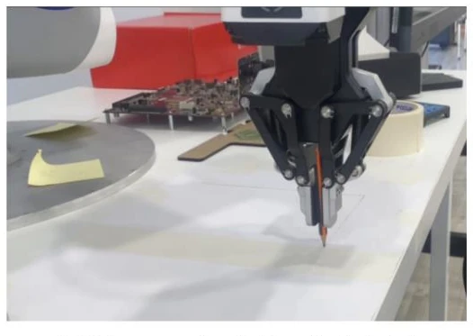
Setting up the physical workstation required aligning the aluminum profile frame relative to the robot's coordinate system. To establish a straight X-axis reference line without optical alignment tools, a pencil was mounted into the cobot’s gripper and guided along the workspace to mark a guide line. The aluminum profiles were then secured to the table using double-sided tape, while the 3D printed tray and JIG base were bolted directly onto the profile rails using standard M5 T-nuts.
On the software side, the control logic in Dobot Studio Pro went through two main iterations. The initial script (v 0.1) relied on manually teaching 20 distinct coordinates for every pick and place location. This was refactored in version 0.2 by implementing the built-in “Create tray” array function, cutting the taught positions down to 10 reference points. To prevent binding during insertion without vision guidance, a passive compliance method was used: the gripper holds the upper portion of each connector with a +1 mm clearance, giving the part enough mechanical float to naturally self-align into the enclosure socket upon contact.
Software Architecture & Control Routine:
Program execution begins with the cobot moving to a predefined home position (1)
and running an automatic gripper initialization sequence that fully closes and opens the jaws to calibrate end-effector limits.
Motion parameters regulate the jaw width, opening to 14mm for approach paths and releasing parts, and closing to 9mm during component engagement to maintain a +1mm passive compliance clearance.
Spatial grid mapping is handled using Dobot Studio Pro’s native "Create tray" block, which instantiates two independent 2D array objects (tray red and tray black). Each array models a 5 X 5 matrix defined by four pre-taught corner points (2 through 5 for red connectors, and 6 through 9 for black connectors).
To prevent unintended contact with adjacent connectors during horizontal transfers, these boundary reference nodes are calibrated on an approach plane 40 mm above the physical tray surface. During extraction, the manipulator indexes to the calculated tray coordinate, performs a relative linear descent of Δ=−40 mm to reach the connector upper body, clamps the part at a 9 mm jaw width, and executes a relative linear ascent of Δ=+40 mm clear of the tray grid.
The component is then transferred toward the enclosure board mounted on the magnetic JIG. Instead of teaching individual coordinates for every socket on the 80×80 mm board, all placement locations are calculated dynamically using relative (, ) coordinate offsets from a single global datum point (10).
Validation and Testing
Validation was conducted through repeated pick-and-place assembly cycles to evaluate mechanical seating, positioning accuracy, and cycle consistency. The test sequence evaluated both connector color sets, running through full extraction from the tray grid to final placement onto the target board held by the magnetic JIG.
Testing verified that the magnetic coupling mechanism maintained consistent JIG registration across multiple board swaps, presenting no measurable positioning shift. Additionally, increasing the gripper width parameter by 1 mm relative to the connector's nominal thickness proved effective for passive compliance. Leaving this slight clearance kept the connector from being held completely rigid, giving it enough mechanical play to self-align and seat fully into the enclosure socket without jamming or applying excess downward force.
Deployment Considerations
Transitioning this proof-of-concept setup from a laboratory environment to a full production floor requires a few physical and operational adjustments. Crucially, the double sided tape used to anchor the aluminum profiles to the workbench must be replaced with permanent mechanical fixtures such as pinned baseplates or direct mounting brackets to prevent long-term alignment drift.
For workspace safety, defined safety zones and tuned power/force limits should be configured for the DOBOT CR3A to ensure safe collaboration during manual board swaps at the magnetic JIG. Additionally, integrating simple hardware part-presence sensors into the feeding tray or gripper would enable basic error detection for missing or dropped connectors, increasing cycle reliability without introducing the cost or complexity of an optical vision system.
Results and Benefits
The implementation of the visionless collaborative assembly workstation yielded several key practical results and operational improvements:
Setup Optimization: Refactoring the positioning logic from manual 20-point teaching down to a structured 10-point array model cut initial workspace calibration time in half while maintaining reliable pick accuracy across all grid positions.
Cost Efficiency: Achieving reliable connector placement using passive mechanical compliance and magnetic JIG registration eliminated the need for external vision hardware and custom tool manufacturing, keeping hardware integration costs minimal.
Assembly Consistency: The magnetic coupling mechanism provided zero-drift board registration across repeated swaps, ensuring consistent seating into predefined enclosure sockets without manual clamping delays or board strain.
Simplicity and Scalability: Utilizing standard Dobot Studio Pro array logic and easily printable 3D fixtures provides a modular blueprint that can be quickly replicated or adapted for other connector types in small-batch manufacturing.
Challenges and Lessons Learned
Open-Loop Trajectory Limits: Operating without vision feedback relies on predictable part placement in the feeding tray, highlighting the functional boundary of purely mechanical positioning.
3D Printing Tolerances: Initial fixture prototypes produced on an FLSUN T1 Pro exhibited dimensional inaccuracies and surface warping that compromised workspace registration. Switching to a Bambu Lab P1S demonstrated that visionless mechanical alignment relies strictly on high-precision printer calibration.
Economic and Industrial Impact
CapEx Reduction: Eliminating external machine vision systems, dedicated lighting, and complex software licenses significantly lowers initial automation costs. This makes collaborative pick-and-place assembly financially feasible for Small and Medium Enterprises (SMEs), pilot lines, and educational facilities with limited budgets.
Rapid Reconfiguration for High-Mix Manufacturing: Utilizing modular 3D-printed fixtures alongside an array-based coordinate model (10 reference points) allows operators to quickly adapt the workstation for different connector layouts or tray configurations without lengthy software reprogramming or high engineering overhead.
Quality Consistency and Ergonomics: Automating repetitive connector insertion removes manual assembly bottlenecks and eliminates fatigue-induced errors. Furthermore, controlling placing force through passive mechanical compliance protects sensitive PCB substrates from physical damage, reducing scrap rates and improving overall yield.
Practical Novelty
Rather than relying on highcost vision systems or force sensors, this setup demonstrates a lean, low-overhead approach to collaborative assembly:
Hardware-Light Alignment: Handles component registration and positioning tolerances strictly through mechanical design using embedded JIG magnets and engineered gripper clearance to eliminate the need for expensive perception hardware.
Streamlined Integration Workflow: Combines simple physical pathing with standard software array functions to minimize setup time and calibration overhead for small-batch assembly deployments
Future Improvements
Vision-Guided Tool Rotation: Integrating a simple external vision sensor will allow the system to detect each connector's rotational offset in the tray. The robot can then utilize its existing wrist axis rotation to orient the component to the exact required angle prior to insertion.
Permanent Table Registration: Replacing the temporary double-sided tape holding the aluminum profile rails with direct-bolted baseplates or locating-pin fixtures will ensure long-term positional stability across extended production runs.
Part-Presence Sensors: Integrating basic optical or tactile part-presence sensors into the gripper jaws will allow the cobot to detect missed picks or dropped connectors without the expense of a full machine vision system.
Conclusions
This project successfully validates a functional, low-cost proof of concept for automated connector assembly using the DOBOT CR3A collaborative robot without relying on expensive machine vision systems. By combining custom 3D-printed physical tooling, near-zero-drift magnetic JIG registration, and structured array-based software logic in Dobot Studio Pro, the workstation achieves consistent pick-and-place execution while cutting calibration overhead in half.
References
[1] Shenzhen Yuejiang Technology Co., Ltd., DOBOT CRA Series Hardware User Guide, Shenzhen, China, 2023. [2] Shenzhen Yuejiang Technology Co., Ltd., Dobot Studio Pro User Guide, Shenzhen, China, 2023.
[3] Shenzhen Yuejiang Technology Co., Ltd., DOBOT CRA Basic Training Manual, Shenzhen, China, 2023.
[4] Dassault Systèmes, SolidWorks 3D CAD Software Documentation, Vélizy-Villacoublay, France, 2023.
[5] Bambu Lab, Bambu Lab P1S 3D Printer User Manual and Specifications, Shenzhen, China, 2023.