The purpose of the Journal is to disseminate knowledge, experience, and best practice in engineering & manufacturing. The articles are written by practicing professionals in the Engineering City (EC). They cover issues relevant to their projects, operations, and organizations. The articles address the challenges of the time. As such, the Journal is also a chronicle of the evolution of the EC, its companies, and its individuals. It is the aim of the Journal to advance the engineering & manufacturing practice, to enrich the engineering & manufacturing community, and to contribute to the worldwide discourse in engineering & manufacturing.
Published by the Engineering Association
The Engineering City JournalIssue 3/2025Published by the Engineering AssociationYerevan, February 11, 2025
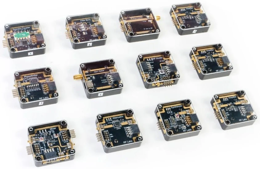
The RF Lab® measurement bench is designed for working with electronic microwave circuits. It allows clear and convenient prototyping, design and investigation of various microwave components and systems.
Convenient and fast circuit assembly - RF Lab is made as a modular construction kit.
A unique feature is the presence of a microcontroller in every electronic component.
Thanks to its high-precision components, it can be used as a measurement system for engineers. Detailed teaching materials.
Purpose and features of RF Lab®
The RF Lab® microwave device prototyping measurement bench is an educational solution for studying and designing microwave components and systems. RF Lab makes it possible to deepen the knowledge base on microwave systems and to prepare students for new technological trends.
Detailed teaching materials have been developed for teachers and students, including laboratory examples and assignments covering the entire spectrum of design.
The RF Lab® measurement bench is a modular construction kit that allows electrical circuits of varying complexity to be assembled quickly for studying and designing microwave components and systems.
The RF Lab® measurement bench makes it possible to carry out laboratory work, measurements and prototyping:
laboratory work to study the fundamentals of microwave circuit design for the following devices:
receiving devices;
transmitting devices;
frequency synthesizers;
multichannel high-frequency transceiver devices;
measurement of the system characteristics of the main RF blocks;
prototyping of a more complex integrated system based on basic radio-frequency blocks;
investigation of the influence of the characteristics of individual HF blocks on the system characteristics of the device;
integration of the basic blocks with an antenna system to study the principles of radar and digital signal processing when integrated with the MOKU system.
The RF Lab® measurement bench can be used to train students in the following specialties:
03.03.03 Radiophysics.
11.03.01 Radio Engineering.
11.03.02 Infocommunication Technologies and Communication Systems.
11.03.03 Design and Technology of Electronic Equipment.
Technical specifications of the RF Lab® bench
operating frequency range: 10 MHz to 6 GHz; maximum input signal level, 10 dBm; Power supply and control USB 3.0 Type C; Type of microwave connectors of the input and output block – SMA Type of microwave connectors of the functional blocks (input – female MMCX, output – male MMCX)
Components of the RF Lab® bench
Each microwave component is housed in a protective enclosure with standard connectors in the form of easily assembled blocks.
The basic RF Lab® kit includes the following set of components:
Input interface block;
Low-noise amplifier;
Power amplifier;
Buffer amplifier;
Frequency converter;
PLL-based frequency synthesizer;
Frequency multiplier and divider;
Microwave filter bank;
Digital attenuator;
Digital phase shifter;
Directional coupler with power detector;
Output block.
The basic kit can be extended with additional HF blocks to expand the functionality of the measurement bench.
Additional functional blocks can be developed and added as they become available.
Each electronic block has a built-in microcontroller and voltage regulator.
Thanks to the built-in microcontroller and voltage regulator, there is no need to connect external power supply and control units.
Configuration and control of the system are implemented in the main microcontroller of the input block, which is connected to a PC via a USB interface.
Configuration and control of the functional blocks are implemented in the internal slave microcontroller.
Communication between the master and the slave is implemented via an I2C interface, which allows up to 128 functional blocks to be connected.
Optionally, each functional block can store measured S-parameters in the microcontroller memory.
Assembly and connection
Thanks to universal connectors, a circuit is assembled and disassembled quickly and effortlessly, and the assembled bench is easily connected to any measuring instruments.
The RF Lab® laboratory measurement bench connects to any measuring equipment; measurement results are processed on a computer using convenient software.
Software
The RF Lab® measurement bench is supplied with intuitive software, which greatly facilitates the learning process.
New Products Corner
Electronics Prototyping Lab – SLAB
by Engineering House LLC
English translation
Slab prototyping board
The SLab electronic circuit prototyping and development board is a set of basic electrical circuits that can be cascaded to create larger functional circuits.
Overview
The SLab board includes basic electrical circuits that can be combined to create more complex functional systems.
The board’s functionality allows it to be used in student training programmes of vocational and higher education institutions for laboratory work, using the teaching guidelines supplied with the kit.
Software
Delta Design, a Russian computer-aided design (CAD) system for printed circuit boards, which allows the full design cycle to be implemented.
In addition
The SLab board has built-in signal sources: DC voltage signals, sinusoidal and square-wave AC signals, pulse-width modulated signals, and it also allows external signal sources to be connected. The generated signals can be observed with an external oscilloscope at various points of the circuits, as well as with the indicators built into the board.
The SLab board for prototyping and developing electronic circuits offers a set of basic electrical circuits that can be combined and joined to create complex functional systems.
SLab - this board provides teachers with all the components needed to carry out project-based experiments in various electronics courses, including power electronics, digital electronics, circuits and measurements.
Special kits of the SLab board + Delta Design CAD have been developed for universities and colleges at favourable prices.
Slab capabilities
Ready-made circuits
The SLab board allows a student to prototype simple analog signal processing circuits and voltage converters, and also to become familiar with logic elements and solutions for converting analog signals to digital form. .
Simulation of the experiment in CAD
Using the SLab board together with Delta Design CAD, the student can simulate the experiment in CAD before prototyping and measuring, and then move on to working with real signals.
Built-in and external signal sources
The work can use both the signal sources built into the board and external signal sources, including audio signals - for example, connecting one’s own phone to play signals and checking how the circuits affect the waveform of the original signal.
.
The SLab board has built-in signal sources: DC voltage signals, sinusoidal and square-wave AC signals, pulse-width modulated signals, and it also allows external signal sources to be connected. The generated signals can be observed with an external oscilloscope at various points of the circuits, as well as with the indicators built into
the board. ,
Kit contents:
SLab electrical circuit prototyping and development board; Power supply; Conductors for external connection; Teaching guidelines; Examples of simulated circuits in the Delta Design, NI Multisim and Altium Designer development environments.
Circuits covered:
Circuits based on passive components and diodes; Transistor audio-frequency power amplifier; Operational amplifier; PWM converter; Matching amplifier; Instrumentation amplifier (measurement of a strain signal using a strain gauge); PWM regulator; Design of circuits with an ADC; Circuits based on digital ICs; Switching regulator; Switching power supply
The SLab board is intended for training students in the following subjects:
Theoretical Foundations of Electrical Engineering, Analog-Digital Circuit Design, Circuit Design of Switching Power Supplies
RF Bench is a new platform for measuring microwave signals.
RF Bench is a set of 6 instruments needed by a radio engineer in a single form factor: a vector signal generator, a vector signal analyzer, a vector network analyzer, a software-controlled power supply, a power sensor and digital input/output. Having all these instruments in one small and portable package allows the user to design, debug and test their radio circuits and systems right on their bench. The included software gives access to all these instruments in a single window.
RF Bench is a new platform for measuring microwave signals.
RF Bench is a set of 6 instruments needed by a radio engineer in a single form factor: a vector signal generator, a vector signal analyzer, a vector network analyzer, a software-
controlled power supply, a power sensor and digital input/output. Having all these instruments in one small and portable package allows the user to design, debug and test their radio circuits and systems right on their bench. The included software gives access to all these instruments in a single window.
Functional capabilities
Hardware:
Vector signal generator
Vector signal analyzer
Vector network analyzer
Power sensor
Software-controlled power supply
Digital inputs/outputs
Software:
Signal generation
Single-tone signal generation
Multi-tone signal generation
Analog modulation (AM/FM/PM)
Signal measurement in the frequency domain
Signal measurement in the time domain
Amplitude-frequency response
S — parameters
Control of the device under test via digital inputs/outputs
Power measurement
Technical specifications
Vector signal generator
Parameter Value
Frequency range 70 MHz to 6 GHz
Frequency step < 1 kHz
Digital-to-analog converter resolution 12 bits
Output power range -70 dBm … 17 dBm
Maximum bandwidth of the generated signal 56 MHz
Number of channels 2
Sample generation rate up to 61,44 MSa/s
Vector signal analyzer
Parameter Value
Frequency range 70 MHz to 6 GHz
Frequency step < 1 kHz
Sample acquisition rate up to 61,44 MSa/s
Maximum input signal power -15 dBm
Gain range 56 MHz
Number of channels 75 dB
Maximum bandwidth of the recorded signal 56 MHz
Number of channels 2
Vector network analyzer
Parameter Value
Frequency range 500 kHz to 4 GHz
Number of channels 2-port, fully bidirectional (measures S11, S12, S21, S22 simultaneously) Dynamic range up to 70 dB in the MHz range, up to 40 dB in the GHz range Frequency adjustment resolution 1 Hz
Number of steps 1 - 10001
Output power -14 dBm at 100 MHz
Power sensor
Parameter Value
Frequency range 1 MHz to 6 GHz
Dynamic range -30 dBm to +20 dBm
Number of channels 1
Power supply
Parameter Value
Voltage range 0 V to 50 V
Current range 0 A to 5 A
Number of channels 2
Digital input/output
Parameter Value
Voltage range -0,5 V to 5,8 V
Number of channels 12
Software, user interface
The program for working with the RF Bench instruments has an intuitive interface.
The user interface gives access to six instruments:
Vector signal generator (Vector Signal Generator);
Vector signal analyzer (Vector Signal Analyzer); (shares one area with the vector network analyzer; switching is done by pressing an on-screen button);
Power sensor (Power Meter);
Power supply (Power Supply);
Vector network analyzer (Vector Network Analyzer) (shares one area with the vector signal analyzer; switching is done by pressing an on-screen button);
Digital input/output (Digital Writer Digital Reader).
Vector signal generator (Vector Signal Generator)
When Vector Signal Generator is started, the window shown below opens.
Main window of the Vector Signal Generator program
Elements of the main window:
1. Channel 0/1 – selects the channel for the generated signal.
2. Center Frequency – frequency of the signal(s). It is set the same for both channels.
3. Gain, dB – input fields for the signal gain of the selected channel.
4. RF ON / RF OFF – starts/stops generation of the selected signal(s).
5. Modulations – enables the modulated signal generation mode.
6. Modulation type – drop-down menu for selecting the modulation mode. The following signal types are possible:
Vector Signal Generator operating mode settings
Vector signal analyzer (Vector Signal Analyzer)
When Vector Signal Analizer is started, the window shown below opens
Vector Signal Analyzer program window
Elements of the main window:
1. Channel 0/1 – selects the channel for the generated signal.
2. CF, MHz – expected frequency of the measured signal(s). It is set the same for both channels.
3. Span, MHh – bandwidth of the analyzed signal
4. RBW, kHz – size of the resolution element.
5. Gain, dB – value of the receive path gain parameter.
Vector network analyzer (Vector Network Analyzer)
1. Switching between spectrum analyzer and network analyzer measurements is done with the Switch to
VNA/VSA
2. When switching to vector network analyzer mode, the calibration settings window opens
Main window of the Vector Network Analyzer program
Description of the Calibration window
In this window, calibration measurements can be performed, saved and loaded. Data acquisition is supported by several algorithms. The Calibration window is organized as a wizard (Wizard). In the first step, the sweep parameters are set. The software then performs the necessary steps. Once all the required data has been collected, the finished window is displayed.
The software has internal temperature compensation, but the results will be best if the device has been warmed up beforehand. This is especially important for frequencies > 2,7 GHz. For higher frequencies, the device should be left connected to the USB port for at least 20 minutes before calibration.
Initial step
Clicking Calibration opens a panel for configuring data acquisition, sweep parameters and the calibration algorithm.
From, MHz – start frequency
To, MHz – stop frequency
Steps – number of frequency steps
Averages – number of averages
Calibration – a combined control containing the supported lists of algorithms
and calibration modes.
Reset to default button – restores the default settings.
Load button – means that an existing calibration file can be loaded and you can go to the Finish step
of the setup wizard.
Start button – runs the setup wizard step by step.
Performing measurements
Measurements tab
Power meter (Power meter)
The Power meter window of the program allows the power of a microwave signal to be measured.
Power meter program window
The main screen of the power meter has the following elements:
1. Measured value (displayed in dBm or mW)
2. Frequency - frequency setting (MHz). displays the entered measurement frequency (the default is 1000 MHz (MHz). After clicking this field, the frequency of the measured signal can be entered. The range of possible measurement frequencies is: 1 MHz to 6 GHz.
If the entered value is below the lower limit of the range, 1 MHz is set.
If the entered value is above the upper limit of the range, 6 GHz is set.
3. Meter operating mode – Low noise/High speed – selects either the measurement mode with a larger measurement aperture and lower noise of the measured value, or the high-speed mode with reduced measurement accuracy Low Noise – 100 ms, High speed – 30 ms.
4. The instrument settings menu is opened with the «≡» icon
Power supply (Power Supply)
After the main program is started, two power supplies are always available to the user.
Power Supply window
Clicking the OK or Cancel button, respectively, saves (applies) the set parameters or cancels the entered changes.
1. Voltage – measured voltage value.
2. Current - measured current value.
3. Wattage - measured power value.
4. Opens the instrument settings menu
5. Power supply status indicator – a green frame when the instrument is operating normally and the output is on.
6. Voltage – set voltage value.
7. Current - set current value
8. On/Off buttons – start the channel.
Digital input/output
By default, the digital input/output works to measure signals. The menu for setting the direction of the lines is opened by pressing the «≡» symbol
Digital input/output window and the instrument’s line direction settings menu